


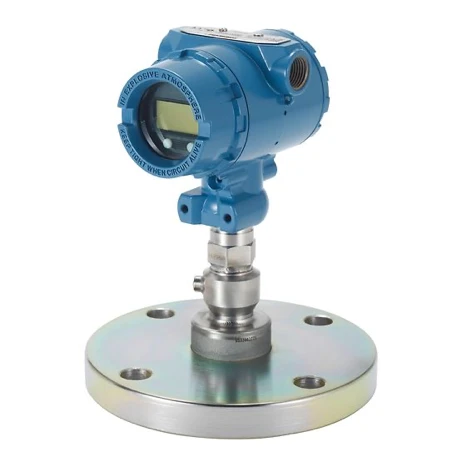
Product introduction:
With the Rosemount 2088 Gage and Absolute Pressure Transmitter, you can keep on schedule with a quick and easy-to-install solution. This transmitter features a Local Operator Interface (LOI) that has easy-to-use menus and built-in configuration buttons, so you can commission the device on the spot without complicated tools. This pressure transmitter is also available with manifolds and remote seals.
Product feature:
- Local Operator Interface (LOI) features straightforward menus and built-in configuration buttons for ease-of-use
- Factory-assembled and leak-checked integral manifold and remote seal solutions deliver a quick start-up
- Available protocols include 4-20 mA HART and 1-5 Vdc HART Low Power for application flexibility
- Lightweight, compact design allows for easy installation
Product Parameter:
Model
|
Code |
Description |
| 2088 | Pressure transmitter |
Pressure type
|
Code |
Description |
| G | Gauge |
| A | Absolute |
Pressure range
|
Code |
(Rosemount 2088G) |
Absolute(Rosemount 2088A) |
|
1 |
-14.7 to 30 psi (-1.01 to 2.1bar) |
0 to 30 psia (0 to 2.1 bar) |
|
2 |
-14.7 to 150 psi (-1.01 to 10.3 bar) |
0 to 150 psia (0 to 10.3 bar) |
|
3 |
-14.7 to 800 psi (-1.01 to 55.2 bar) |
0 to 800 psia (0 to 55.2 bar) |
|
4 |
-14.7 to 4000 psi (-1.01 to 275.8 bar) |
0 to 4000 psia (0 to 275.8 bar) |
|
5 |
-14.7 to 10000 psi(-1.0 to 689 bar) |
0 to 10000 psia (0 to 689 bar) |
Transmitter output
HART Revision 5 is the default HART output. The Rosemount 2088 with selectable HART can be factory or fieldconfiaured to HART Revision 7, To order HART Revision 7 factory confiaured, add option code HR7.
|
Code |
Description |
|
S |
4-20 mA dc/Digital HART Protocol |
|
N |
1-5 Vdc Low Power/Digital HART Protocol |
Product certifications
Valid when SuperModule"Platform and housing have equivalent approvals.
|
Code |
Description |
|
E1 |
ATEX Flameproof |
|
I1 |
ATEX Intrinsic Safety |
|
IA |
ATEX FISCO Intrinsic Safety; for FOUNDATON Fieldbus or PROFIBUS PA Protocol only |
|
N1 |
ATEX Type n Certification |
|
K8 |
ATEX Flameproof, Intrinsic Safety, Type n, Dust (combination of E8, 11 and N1) |
|
E4 |
japan Flameproof |
|
E5 |
USA Explosion-proof, Dust ignition-proof |
|
I5 |
USA Intrinsically Safe; Nonincendive |
|
K5 |
USA Explosion-proof, Dust lgnition-proof, intrinsically Safe, Division 2 |
|
E6 |
Canada Explosion-proof, Dust lgnition·proof, Division 2 |
|
I6 |
Canada intrinsically Safe |
|
C6 |
Canada Explosion-proof, Dust ignition-proof, Intrinsically Safe, and Division 2 |
|
K6 |
Canada Explosion-proof, Intrinsically Safe, and Division 2 (combination of E6 and 16) |
|
E7 |
IECEx Flameproof |
|
I7 |
lECEx Intrinsic Safety |
|
IG |
IECEx FISCO Intrinsically Safe; for FOUNDATION Fieldbus or PROFIBUS PA Protocols only |
|
N7 |
IECEx Type n Certification |
|
K7 |
IECEx Flameproof, Dust lgnition-proof, intrinsic Safety, and Type n (combination of 17, N7, and E7) |
|
E2 |
Brazii Fiameproof |
|
I2 |
Brazil intrinsic Safety |
|
IB |
Brazil FiSCO intrinsically safe; for FoUNDATON Fieldbus or PROFIBUS PA Protocols only |
|
K2 |
Brazil Flameproof, intrinsic Safety |
|
E3 |
China Flameproof |
|
I3 |
China intrinsic Safety |
|
EP |
Republic of Korea Flameproof |
|
IP |
Republic of Korea intrinsic Safety |
|
KP |
Republic of Korea Flameproof, Intrinsic Safety |
|
EM |
Technical Regulations Customs Union (EAC) Flameproof |
|
IM |
Technical Regulations Customs Union (EAC) intrinsic Safety |
|
KM |
Technical Regulations Customs Union (EAC) Flameproof, intrinsic Safety |
|
KB |
USA and Canada Explosion-proof, Dust lgnition-proof, intrinsically Safe, and Division 2 (combination of K5 and C6) |
|
KD |
USA, Canada, and ATEX Explosion-proof, Intrinsically Safe (combination of K5, C6, 11, and E8) |
|
KL |
USA, Canada, IECEx, ATEX Intrinsic Safety Combination |
|
KS |
USA, Canada, IECEx, ATEX Exploslon Proof, intrinsically Safe, Dust, Non-incendive, Type-N, Division 2 |
Dimensional drawings
Transmitter with coplanar module
Dimensions are in inches (millimeters).
Figure 3: Optional Digital Display
A. Digital display cover
B.2½-14 NPTconduit connection
Note
Dimensions are in inches (millimeters).

Figure 4: Process Connection
A. Field terminals
B.Conduit connection
C.Transmitter electronics
D.½-14 NPTfemale connection
Note
RC ½ female (PT ½ female), and M20 female also available as options.

Figure 5: Nameplate and Labels
A. Bracket mounting holes (¼-20 UNC)B. Nameplate
C. Certification label (located on side)
Note
Dimensions are in inches (millimeters).

Figure 6: Optional pipe Mounting Bracket
A. 2-in. U-bolt for pipe mounting (clamp shown)
B.1%bolts for transmitter mounting

Figure 7: Optional Panel Mounting Bracket
A,¼X1¼ bolts fortransmitter mounting
B. 5/16 X 1½ bolts for panel mounting (not supplied)
Note
Dimensions are in inches (millimeters)

Hot Tags: 2088 pressure transmitter, China 2088 pressure transmitter suppliers, factory, differential pressure sensor, differential pressure transmitter, pressure safety transmitter, precision pressure transducer, differential pressure transmitter 984m, air pressure transmitter


